by craig | Nov 5, 2026 | articles
Due to its price tag, size, and power consumption, the Synclavier II was always the reserve of pro studios. As an individual, you’d have to achieve the kind of success Michael Jackson, Frank Zappa, or Sting enjoyed, to justify owning one.
It’s estimated just over one thousand were sold during the product’s lifetime. Not a huge amount, certainly when compared to other keyboards of the era, such as the Roland Juno or Yamaha DX7. Of those 1000, around 200 are still in operation. That’s pretty good for a synth that’s just had its 43rd birthday.
The owners range from – composers that used Synclavier II extensively back in the eighties to, well, do their job, and couldn’t bear to part with it, even when they had amassed more compact and convenient synthesizers – to newer, younger synth enthusiasts who are hungry for that “Synclavier” sound.
These brave few must perform regular maintenance, occasionally scouring the internet for spare parts, and, in some locales, hoping when the next brown-out occurs on the power-grid, they only blow a fuse and not something more important.
It’s unsurprising then, that since the closure of NED, Cameron Jones has regularly fielded the question, “are you going to make another hardware Synclavier?”
Cameron got pretty good at deflecting it over the years, by quickly changing the subject, but in early 2020, between COVID-19 lockdowns, he and Craig Phillips, with whom he had collaborated with on the Synclavier Knob product, were sat drinking coffee and contemplating giving his customers what they’d so often asked for.
They’d just successfully ported the Synclavier synth engine to Linux. It took less than a week. “Well, that was easy,” said Cameron, “maybe it is time to do another hardware version.”
Nowadays there’s a proliferation of embedded compute modules that run Linux. Cameron tasked Craig with researching the specs of these modules to see if any of them were up to the task of being the new brain of Synclavier, just, “for fun,” as he put it.
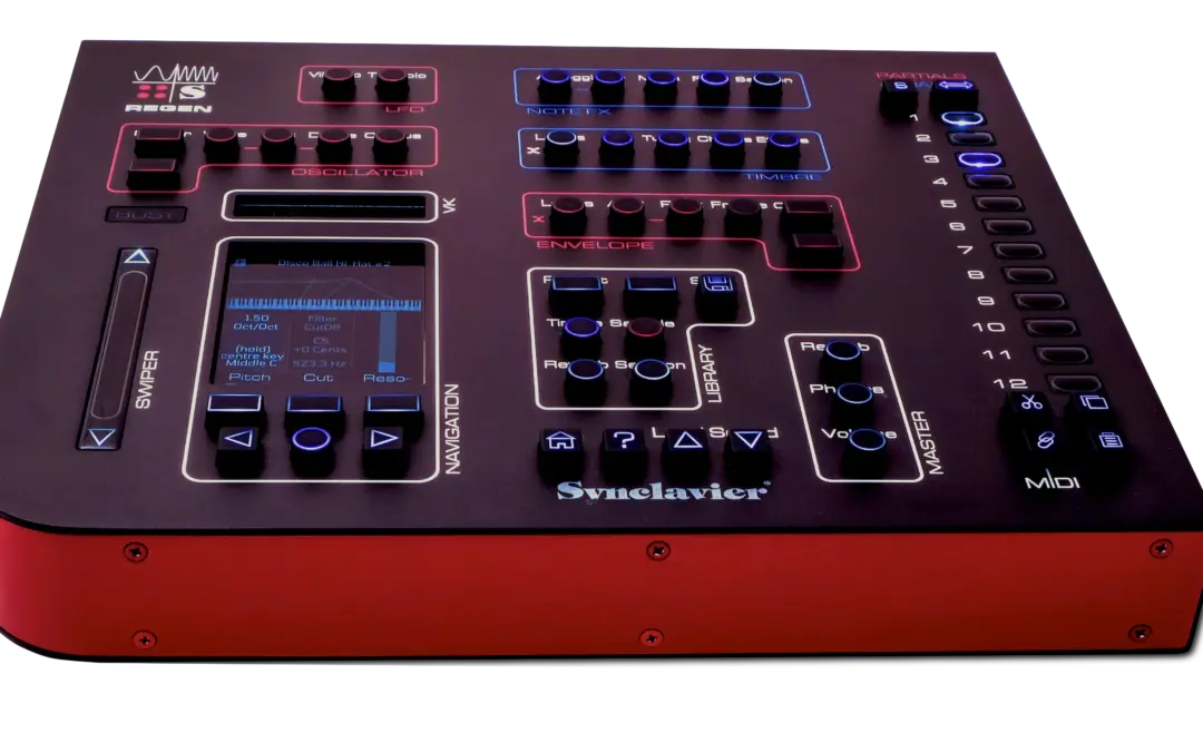
And so began the development of Synclavier Regen.
Craig had just had a baby and his wife was on maternity leave for 12 months. “You better have it finished and generating income when I go back to work,” she said. “Because you’ll be looking after our daughter then.”
“No problem,” replied Craig.
It took over two years to develop. Still, pretty impressive for a two-man team. Craig had to juggle many evenings and weekends, but thankfully his baby was a good sleeper, otherwise there may never have been a Regen.
A desktop incarnation certainly seemed like the right product category. It would require less development time, and carry less financial risk, than a full-sized synth with a keyboard, but still present an enticing prospect for a would-be customer; it was thought that for the vast majority of customers, Regen wouldn’t be their first synth, so the assumption was they’d already have a suitable MIDI keyboard to use with it.
After selecting a powerful multi-core compute module, the most important task was to get the sound right. This meant creating a capable DAC circuit with a careful PCB layout and sourcing high-quality components.
Cameron had tested a number of off-the-shelf DACs of various costs. Some had an excellent frequency response linearity, but quite a bit of noise. Others had low noise floor, but bad frequency response.
When he tested the first prototype Craig provided, he ran his set of tests while Craig waited with bated breath. Cameron finally spoke. “The frequency response is the best I’ve tested.”
“And what about the noise floor?” asked Craig.
“It’s low. Very low. I think the noise I’m seeing is probably from my measuring equipment.” Cameron smiled. “I think we have a product here.”
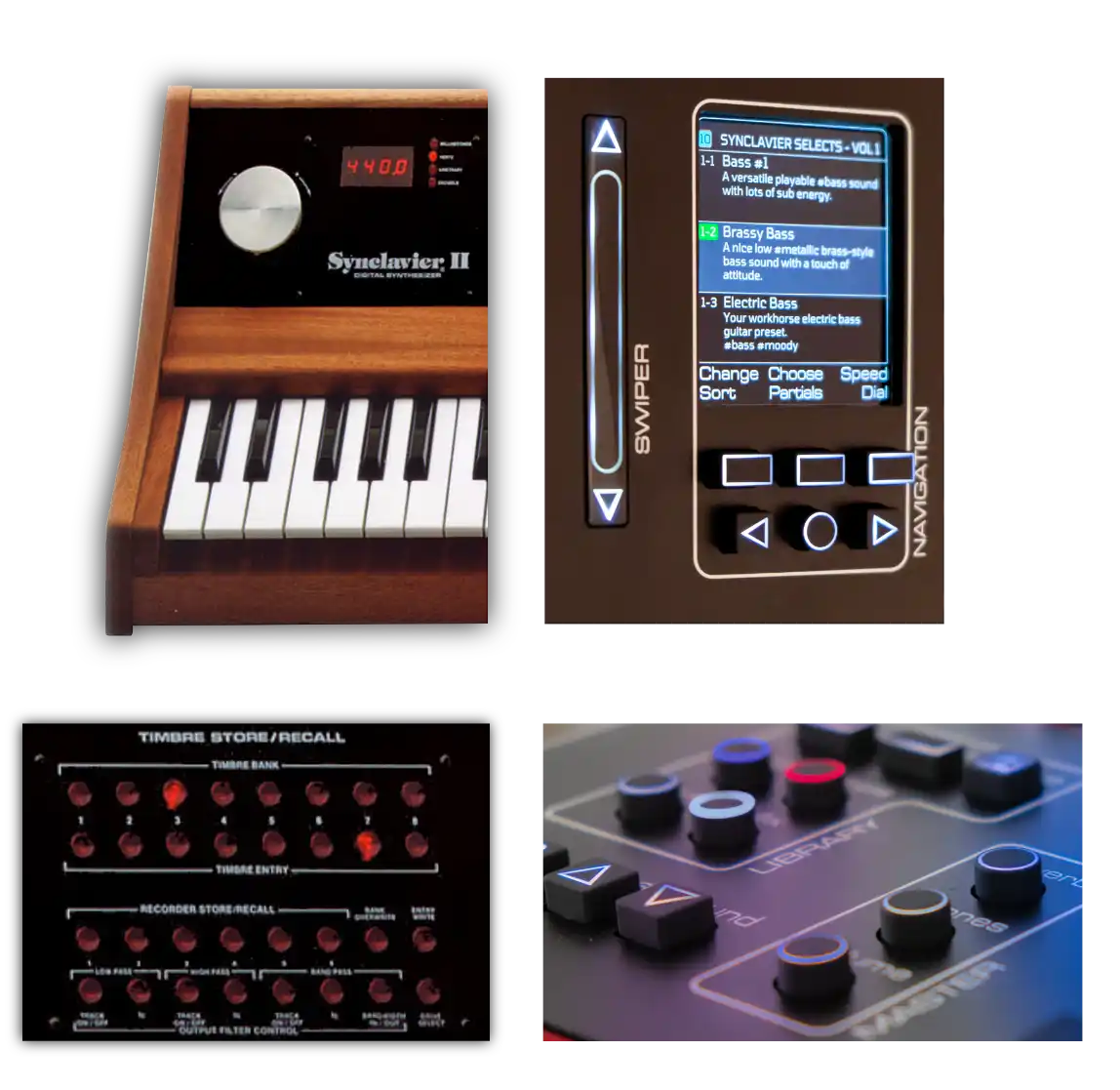
Old and new: Synclavier Knob and “red” buttons.
The Synclavier II had 160 buttons; way too many for a desktop incarnation. After eliminating a few ideas, they were able to settle on a panel layout for Regen with 50 buttons plus the 12 selector buttons.
Pressing a function button from one of Regen’s seven “panels” brings the function’s “page” to the screen and reveals its three parameters on the “soft” option buttons below the screen. If a function has more than three parameters, you have to navigate left or right to reveal more, typically less-often-used, parameters. This seemed like the best compromise between buttons and useability, and, importantly, doesn’t feel like (the dreaded) menu-diving most of the time. Some menu diving was inevitable: the Filter, Effects and Define buttons, with their multitude of settings, do harbour subpages.
“The way, we’ve laid it out,” says Cameron, “there’s enough spacing that you don’t go accidentally hitting the wrong button. We really didn’t want it to be fiddly. And the way Craig has done the panel borders and colour-coding, it really helps your brain and muscle memory, which is always important for a musical instrument.”
Another thing Craig did, was to refresh the look of the buttons. The original red buttons with little Fresnel lenses aren’t available now. Cameron had requested that Craig model them, and use modern manufacturing techniques to produce something similar, as he had done with the knob, but that idea was soon dismissed in favour of an updated look that had a nod to the original.
The outlined button shapes are laser-etched in the silicone and back-lit by LEDs. It would’ve been easier to source one white LED and colour the buttons themselves, but this approach gives the buttons a satisfying otherworldly glow, especially in a darkened room, and it has the side-benefit that some of the buttons can switch colour based on function by using a RGB LEDs.
All this had to be designed, prototyped, redesigned and perfected. The value Swiper was something that Craig and Cameron had to get right. The Synclavier synth engine has a such a symbiotic relationship with the knob, that if they were to have the audacity to offer an alternative, it better work well.
With a combination of a state-of-the-art capacitive touch chip and Cameron’s custom hysteresis software, they were able produce something that was reliable and accurate, and slick: a real joy to use. Such was the success of the new vertical Swiper, that Cameron insisted that the 12 selector buttons be implemented in the same way.
A boon of Synclavier II was the swipe-able nature of those iconic red buttons. Being able to quickly select several partials at once then change their parameters in unison was something both intuitive and efficient. Something trivial to recreate decades later on the touch screen of the iPad app, Synclavier Go! It turns out it’s much harder to do this effectively with multi-coloured LEDs in the vicinity of the touch pads, creating lots of stray capacitance. Indeed, Synclavier Digital’s patent application for Regen covers the engineering of the Swiper and Selector buttons. It took 4 iterations of PCB to get the Selector buttons working correctly and the finer points of how this was achieved will remain a trade secret.
With the interface perfected, Cameron spent many hours on graphics software for the screen. “Having that much more real-estate than its predecessor,” says Cameron, “and Regen’s screen being multicolour, it would’ve been a crime not to make good use of it.”
Cameron coded graphical representations of everything: modulation mapping functions, filter response curves, keyboard ranges, and so on, all making the machine easier to use. It quickly became, not only an evolution of the original, but truly its own instrument, hence the name, Regen.
“Looking at this synth now,” says Craig, “and the complexity of it, both hardware and software, it seems unreal that we completed the development. But, back when Cameron and Sydney Alonso were working on Synclavier II together, that was a monumental achievement too.
“During the two years, we hit many brick walls; if I hit one and ran out of steam, Cameron would chip away at the problem; if he hit one, I would take a swing for a while. We work together very well and I’m extremely proud of what we’ve built.”
The finished product certainly has that feel of a boutique synth crafted by a small team of people that care, rather than a device specified by committee to hit a certain price point. It has “soul” as Loopop put it in the first video featuring Regen to hit YouTube.
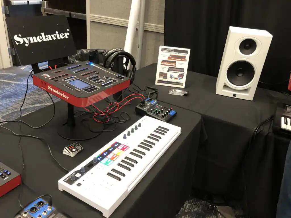
The Synclavier corner at Synthplex 2022 where Regen made its first public appearance
Having such a small team, meant they were able to keep it under wraps until its launch at Synthplex back in October. “The first day,” says Craig, “people were walking by us without so much of a glance. But I think the surprise launch caused a lot of internet chatter, and by the Sunday, people were seeking out our booth. We were inundated with visits from musicians, producers, hobbyists, movie composers, other synth manufacturers, and journalists. And pre-orders were rolling in, which was something of a relief; it’s one thing knowing you have a fantastic product, but it’s another thing to convince other people.”
Cameron enjoyed the experience at Synthplex. And when he met with many of his existing customers, he no longer had that question to deflect.
More information on Regen can be found here.
by craig | Mar 23, 2026 | manual
Intro
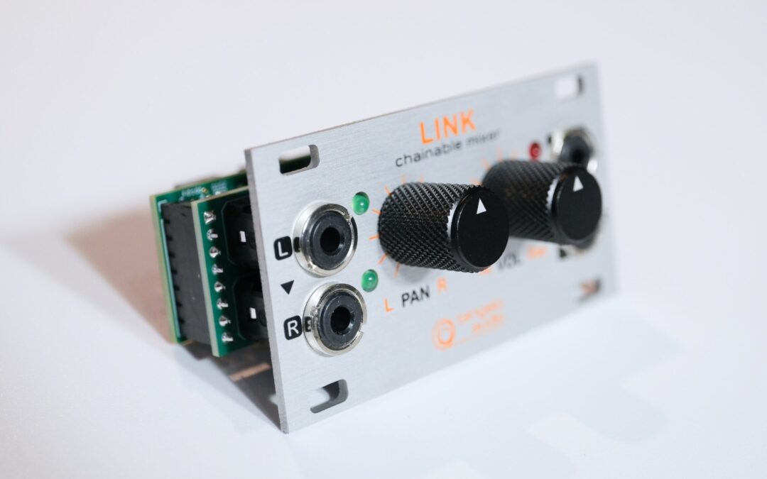
The LINK module is a stereo mixer element. Several LINKS are chained together to make a multi-channel mixer. LINK requires a compatible Eurorack case to operate.
The LINK circuit is an all-analogue design using high-quality components and a carefully considered layout.
What’s in the box
- LINK Eurorack module in anti-static packaging
- 6″ 16-pin IDC to 10-pin IDC connector cable
- A 10cm JST PH2.0 3-pin female to female straight daisy-chain cable
- 4 x M3 cheese head screws
- A QR code to this online manual
Circuit Technicals
The electronic circuit has been designed for zero colouration of the audio path. Inputs are ESD-protected and buffered for hIgh-impedance input. This stage is followed by the sine/cosine law panning circuitry and then the logarithmic volume control. Input signals and clipping meters are driven off a buffered audio path, using a separate power supply branch to avoid crosstalk. High-quality OPA1679 op-amps are used on the signal path for superior headroom and fidelity.
Installation
Use the included cabling to connect your LINK module/s:
- Turn off the power supply to your Eurorack rig before installing or uninstalling modules and take anti-static precautions (such as using a grounding mat and removing footwear with rubber soles).
- Connect the IDC power cable/s to your Eurorack case (the 16-pin side), ensuring correct polarity. The Red stripe on the cable corresponds to Pin 1 on the IDC connectors (Pin 1 provides to -12V power).
- The 10-pin side of the cable connects to LINK. (NB: Depending on your set-up, it may be easier to connect all the power cables to your LINKs first or the daisy-chain cables first.) The 10-pin power connector shroud on LINK is notched to make incorrect mating very unlikely. Nevertheless, it’s always worth checking that the red stripe on the cable aligns with the white line and -12V legend on the PCB silkscreen.
Make the chain:
- Connect the daisy-chain cables between each LINK. The length of the provided daisy-chain cable is good for LINKs next to each other in your rack. If you wish to have LINKs further apart, you’ll need longer daisy-chain cables. Tangelo Support can assist with this if necessary.
- The sockets for the daisy-chain cables are notched to prevent incorrect mating. And it doesn’t matter which end of the cable goes to which socket.
- Connect a daisy-chain cable from CHAIN-OUT on the first module to CHAIN-IN on the next module.
- For any intermediate modules, connect CHAIN-OUT to CHAIN-IN with an additional daisy-chain
- For the last module, connect a daisy-chain from the CHAIN-OUT of the previous module to LAST-IN on the final module.
- In the case of a chain of two, connect the CHAIN-OUT of the first module to LAST-IN on the final module.
- In the case of using one solitary LINK, no daisy-chain cables are required.
Almost ready:
- When all the cables are securely installed, carefully slot the modules into their positions and secure them with the M3 cheese-head screws.
Operating Instructions
Ready to use.
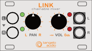
- Each LINK has two input sockets on the left-hand side. For mono sources, just connect to the L socket. For stereo sources, use L and R.
- The green LEDs adjacent to the inputs glow faintly to indicate the unit is powered up. The brightness varies with the input signal, so when an audio signal is coming into the unit, you will see these LEDs pulsate.
- Set PAN to your desired position. At the centre position, you will feel a detent to indicate centre panning. When you adjust the balance left and right, the weighting follows a sine/cosine law for naturalness. Fully counter-clockwise, the signal will only go to the left channel; fully clockwise, the signal will only go to the right channel.
- Adjust the VOL control to your desired level. Fully clockwise represents unity level, where the signal leaving the unit is the same amplitude as that entering. As you turn the knob counterclockwise, the attenuation follows a logarithmic law. Fully counter-clockwise represents -60dB.
- The PAN and VOL controls only affect the signal coming into their LINK. Signals coming in from LINKS prior in the chain are not affected.
- The red LEDs to the right of the VOL control are clipping meters. In normal operation, you should not see these LEDs light up. As many signals are added to a chain, especially if they have coherent material, you may see these flicker red, in which case you’ll need to turn down the volume.
- For the stereo mixer output, plug into the L and R outputs of the final LINK in your chain.
- Outputs from prior LINKs can be used – they’re fully-buffered in-phase outputs – but they’ll only contain the signals from their LINK. You may find legitimate uses for this, such as creating aux mixes or effects buses.
Technical Specifications
- 1U height (39.65mm Intellijel format), 14HP horizontal pitch
- 2mm anodized aluminium front panel
- 40mm depth (including power connector, not including faceplate)
- black-anodized aluminum knurled knobs
- Current Draw: 12mA on +12V rail and 12mA on -12V rail
- Input impedance: 100k ohms
- Output impedance: 100ohms
- THD (at 1kHz): -105dB
- Dynamic Range: 119.5dB
- Noise Floor (100 Hz–20 kHz): –104 dBu RMS
This unit conforms to RoHS requirements. Please dispose of it at a recycling facility capable of processing electronics and PCBs for proper treatment, recovery, and recycling in accordance with your national legislation and the Directive 2012/19/EU (WEEE – Directive on Waste Electrical and Electronic Equipment).
The packaging has been marked in accordance with Triman requirements. The packaging consists of cardboard and polypropylene, both of which are widely accepted for recycling.
This equipment has been tested and found to comply with the limits for a Class B digital device, pursuant to part 15 of the FCC Rules and Canadian ICES-003. These limits are designed to provide reasonable protection against harmful interference in a residential installation. This equipment generates, uses, and can radiate radio frequency energy and, if not installed and used in accordance with the instructions, may cause harmful interference to radio communications. However, there is no guarantee that interference will not occur in a particular installation.
This device has been tested and found to comply with the limits of the European Council Directive on the approximation of the laws of the member states relating to Radio Equipment Directive 2014/53/UE.
This device has been tested and complies with the essential requirements of the Radio Equipment Regulations 2017 (S.I. 2017/1206).
by craig | Jan 16, 2026 | manual
Intro
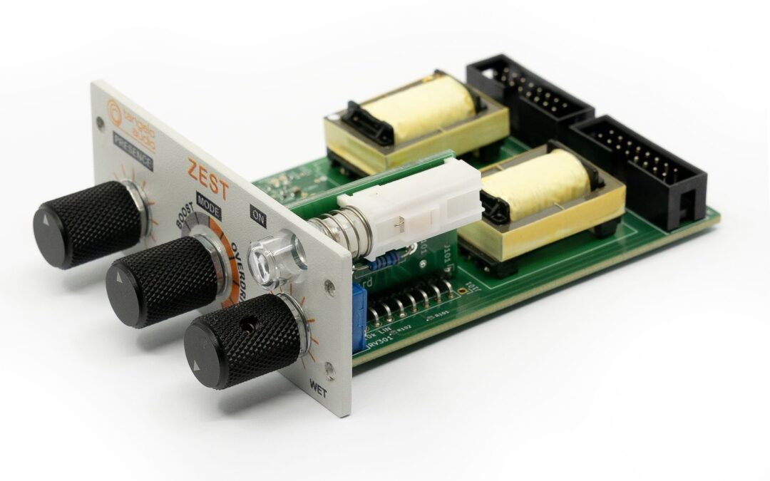
The ZEST module is a presence effect. It cannot be used standalone, but is used within 100 series racks and enclosures.
The ZEST circuit is an all-analogue design based on a transformer saturation effect with a twist.
What’s in the box
- 100 series ZEST module in anti-static packaging
- 5″ 16-pin IDC connector cable
- 4 x M3 cheese head screws
- A QR code to this online manual
Circuit Technicals
A typical transformer in saturation exhibits some even-order harmonic distortion, particularly noticeable on the bass end of the frequency spectrum, which results in a pleasant mellow effect.
The transformers in ZEST are driven a little differently, and the circuit exhibits both even and odd harmonic distortion throughout the frequency spectrum (odd being more prominent), particularly noticeable in the treble end of the spectrum, which creates a “presence” effect where the listener feels more engaged with the music.
How to Use it
This module will be installed into a 100-series compatible host, such as a modular mixer or desktop enclosure. Follow the host instructions for installation. Always shut off power to an enclosure before removing panels and installing modules. You will use the included 16-pin IDC cables to create a “loop” through all your connected equipment. There are notches on the cable plugs and sockets to ensure proper orientation. A good check to remember is that the red wire on one end of the cable denotes pin 1. Pin 1 is typically also denoted on the silkscreen of the PCB with a circular blob next to that pin. When fitted, ensure that no part of the module PCB is touching any bare metal or loose cables. Any electrical short could damage your equipment.
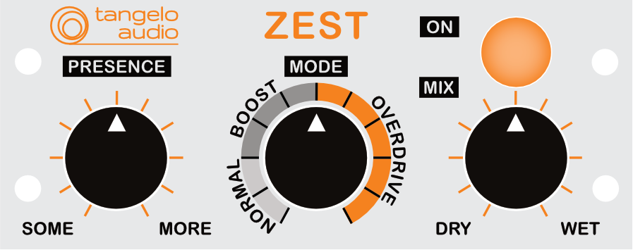
The Pushbutton on the top-right, labelled ON, is the ON/OFF button. This toggles between the effect being engaged or bypassed. When the button is lit, this indicates the effect is active; when unlit, the effect is bypassed. It is a true bypass and the ZEST circuitry is not involved in the signal path.
The two leftmost knobs are sound design controls and the rightmost knob is a mix amount. When first orienting yourself with ZEST, a recommended strategy would be to crank the third knob clockwise to full WET setting, play with the first two controls to hear what the effect does, then dial back the WET/DRY to a suitable level.
The lines on the knob legends are there so you can recall a previous setting. Since the face of a 100 series is small, values were not added to these lines to prevent a crowded look. You may wish to think of the sound design knobs going from 1 to 11, with 6 being halfway, and the third knob as going from 0% to 100% with 50% being halfway.
The knob labelled PRESENCE controls the intensity of the effect. Fully anti-clockwise, the effect is there, but subtle. Turning it clockwise doesn’t create more harmonics, but intensifies the ones created by the circuit. As a guide, with a typical signal of 2.3V RMS, fully turning this knob will increase the harmonic distortion by about 10dB. If you desire even more harmonics, you can run the signal hotter into ZEST.
As you change the PRESENCE control, you will also change phase reinforcement and cancellation of various frequencies, caused by the transformer circuit, and you should hear certain sounds pop out more. This is particularly useful if sounds are getting lost in a mix and adjusting channel volume is too blunt a tool. For example, for a percussion sound, you may find it starts to “pop” at level 1 or 2, whereas a synth sound may require 5 or 6 to become more focused in the mix. You have to play with it a little to discover what level works for what sound.
The nature of the effect circuitry means that with all the additional harmonics, it can sound bright with certain source material. That is where the MODE control comes in. The effect output can be fine-tuned with this knob. In the normal zone, the brighter transformer output will be blended with an appropriate amount of low-end to create a balanced sound. When you head into the boost section, the transformer circuit is stronger by a dB or so and the low-end correspondingly weaker. The sound is not as balanced: in terms of frequency response, its titlted up slightly from about 3kHz and tilted down slightly below it. If you’re using this effect to gain presence, this zone might be exactly what you want.
When the MODE is in the overdrive zone, the frequency response tilts up from 3kHz upwards steeper than that of the boost zone, and frequencies from about 1kHz to 3kHz are dragged up too. So you get the same level of lows in overdrive mode, but mids and highs have been enhanced, leading to a perceived volume increase – hence the term overdrive.
The WET/DRY is a mix control that changes the amount of the effect that you hear from the ZEST module. For example, at 50%, the effect is mixed in equal parts with the DRY (bypassed) signal. You decide how much of the effect you want to shine through. For some instruments or source material, only a whisker will be required, and you may set it at 10%, but othertimes, you may want to crank ZEST to 100% to really hear it perform its magic.
NB: Another way to view these controls, which might fit better in guitar pedal parlance, would be INTENSITY, TONE, and AMOUNT.
Technical Specifications
- 6HP module height
- 2mm aluminium front panel, powder-coated in marine grey
- black-anodized aluminum knurled knobs
- Input impedance: 100k ohms
- Output impedance: 100ohms
- THD (at 1kHz): -108dB
- Dynamic Range: 117dB
- Noise Floor (100 Hz–20 kHz): –96.7 dBu RMS
This unit conforms to RoHS requirements. Please dispose of it at a recycling facility capable of processing electronics and PCBs for proper treatment, recovery, and recycling in accordance with your national legislation and the Directive 2012/19/EU (WEEE – Directive on Waste Electrical and Electronic Equipment).
The packaging has been marked in accordance with Triman requirements. The packaging consists of cardboard and polypropylene, both of which are widely accepted for recycling.
This equipment has been tested and found to comply with the limits for a Class B digital device, pursuant to part 15 of the FCC Rules and Canadian ICES-003. These limits are designed to provide reasonable protection against harmful interference in a residential installation. This equipment generates, uses, and can radiate radio frequency energy and, if not installed and used in accordance with the instructions, may cause harmful interference to radio communications. However, there is no guarantee that interference will not occur in a particular installation.
This device has been tested and found to comply with the limits of the European Council Directive on the approximation of the laws of the member states relating to Radio Equipment Directive 2014/53/UE.
This device has been tested and complies with the essential requirements of the Radio Equipment Regulations 2017 (S.I. 2017/1206).