Intro
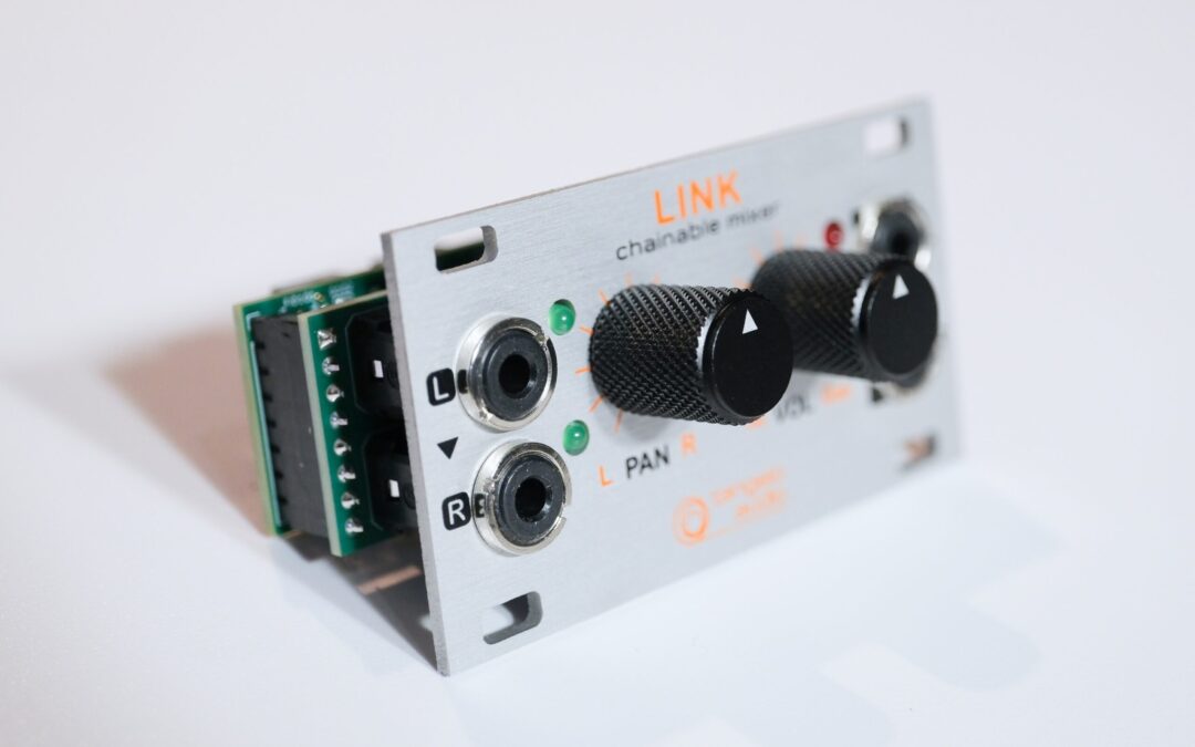
The LINK module is a stereo mixer element. Several LINKS are chained together to make a multi-channel mixer. LINK requires a compatible Eurorack case to operate.
The LINK circuit is an all-analogue design using high-quality components and a carefully considered layout.
What’s in the box
- LINK Eurorack module in anti-static packaging
- 6″ 16-pin IDC to 10-pin IDC connector cable
- A 10cm JST PH2.0 3-pin female to female straight daisy-chain cable
- 4 x M3 cheese head screws
- A QR code to this online manual
Circuit Technicals
The electronic circuit has been designed for zero colouration of the audio path. Inputs are ESD-protected and buffered for hIgh-impedance input. This stage is followed by the sine/cosine law panning circuitry and then the logarithmic volume control. Input signals and clipping meters are driven off a buffered audio path, using a separate power supply branch to avoid crosstalk.
Installation
Use the included cabling to connect your LINK module/s:
- Turn off the power supply to your Eurorack rig before installing or uninstalling modules and take anti-static precautions (such as using a grounding mat and removing footwear with rubber soles).
- Connect the IDC power cable/s to your Eurorack case (the 16-pin side), ensuring correct polarity. The Red stripe on the cable corresponds to Pin 1 on the IDC connectors (Pin 1 provides to -12V power).
- The 10-pin side of the cable connects to LINK. (NB: Depending on your set-up, it may be easier to connect all the power cables to your LINKs first or the daisy-chain cables first.) The 10-pin power connector shroud on LINK is notched to make incorrect mating very unlikely. Nevertheless, it’s always worth checking that the red stripe on the cable aligns with the white line and -12V legend on the PCB silkscreen.
Make the chain:
- Connect the daisy-chain cables between each LINK. The length of the provided daisy-chain cable is good for LINKs next to each other in your rack. If you wish to have LINKs further apart, you’ll need longer daisy-chain cables. Tangelo Support can assist with this if necessary.
- The sockets for the daisy-chain cables are notched to prevent incorrect mating. And it doesn’t matter which end of the cable goes to which socket.
- Connect a daisy-chain cable from CHAIN-OUT on the first module to CHAIN-IN on the next module.
- For any intermediate modules, connect CHAIN-OUT to CHAIN-IN with an additional daisy-chain
- For the last module, connect a daisy-chain from the CHAIN-OUT of the previous module to LAST-IN on the final module.
- In the case of a chain of two, connect the CHAIN-OUT of the first module to LAST-IN on the final module.
- In the case of using one solitary LINK, no daisy-chain cables are required.
Almost ready:
- When all the cables are securely installed, carefully slot the modules into their positions and secure them with the M3 cheese-head screws.
Operating Instructions
Ready to use.
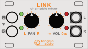
- Each LINK has two input sockets on the left-hand side. For mono sources, just connect to the L socket. For stereo sources, use L and R.
- The green LEDs adjacent to the inputs glow faintly to indicate the unit is powered up. The brightness varies with the input signal, so when an audio signal is coming into the unit, you will see these LEDs pulsate.
- Set PAN to your desired position. At the centre position, you will feel a detent to indicate centre panning. When you adjust the balance left and right, the weighting follows a sine/cosine law for naturalness. Fully counter-clockwise, the signal will only go to the left channel; fully clockwise, the signal will only go to the right channel.
- Adjust the VOL control to your desired level. Fully clockwise represents unity level, where the signal leaving the unit is the same amplitude as that entering. As you turn the knob counterclockwise, the attenuation follows a logarithmic law. Fully counter-clockwise represents -60dB.
- The PAN and VOL controls only affect the signal coming into their LINK. Signals coming in from LINKS prior in the chain are not affected.
- The red LEDs to the right of the VOL control are clipping meters. In normal operation, you should not see these LEDs light up. As many signals are added to a chain, especially if they have coherent material, you may see these flicker red, in which case you’ll need to turn down the volume.
- For the stereo mixer output, plug into the L and R outputs of the final LINK in your chain.
- Outputs from prior LINKs can be used – they’re fully-buffered in-phase outputs – but they’ll only contain the signals from their LINK. You may find legitimate uses for this, such as creating aux mixes or effects buses.
Technical Specifications
- 1U height, 14HP horizontal pitch
- 2mm anodized aluminium front panel
- 40mm depth (including power connector, not including faceplate)
- black-anodized aluminum knurled knobs
- Input impedance: 100k ohms
- Output impedance: 100ohms
- THD (at 1kHz): -105dB
- Dynamic Range: 119.5dB
- Noise Floor (100 Hz–20 kHz): –104 dBu RMS
This unit conforms to RoHS requirements. Please dispose of it at a recycling facility capable of processing electronics and PCBs for proper treatment, recovery, and recycling in accordance with your national legislation and the Directive 2012/19/EU (WEEE – Directive on Waste Electrical and Electronic Equipment).
The packaging has been marked in accordance with Triman requirements. The packaging consists of cardboard and polypropylene, both of which are widely accepted for recycling.
This equipment has been tested and found to comply with the limits for a Class B digital device, pursuant to part 15 of the FCC Rules and Canadian ICES-003. These limits are designed to provide reasonable protection against harmful interference in a residential installation. This equipment generates, uses, and can radiate radio frequency energy and, if not installed and used in accordance with the instructions, may cause harmful interference to radio communications. However, there is no guarantee that interference will not occur in a particular installation.
This device has been tested and found to comply with the limits of the European Council Directive on the approximation of the laws of the member states relating to Radio Equipment Directive 2014/53/UE.
This device has been tested and complies with the essential requirements of the Radio Equipment Regulations 2017 (S.I. 2017/1206).